


 English
 中文简体
中文简体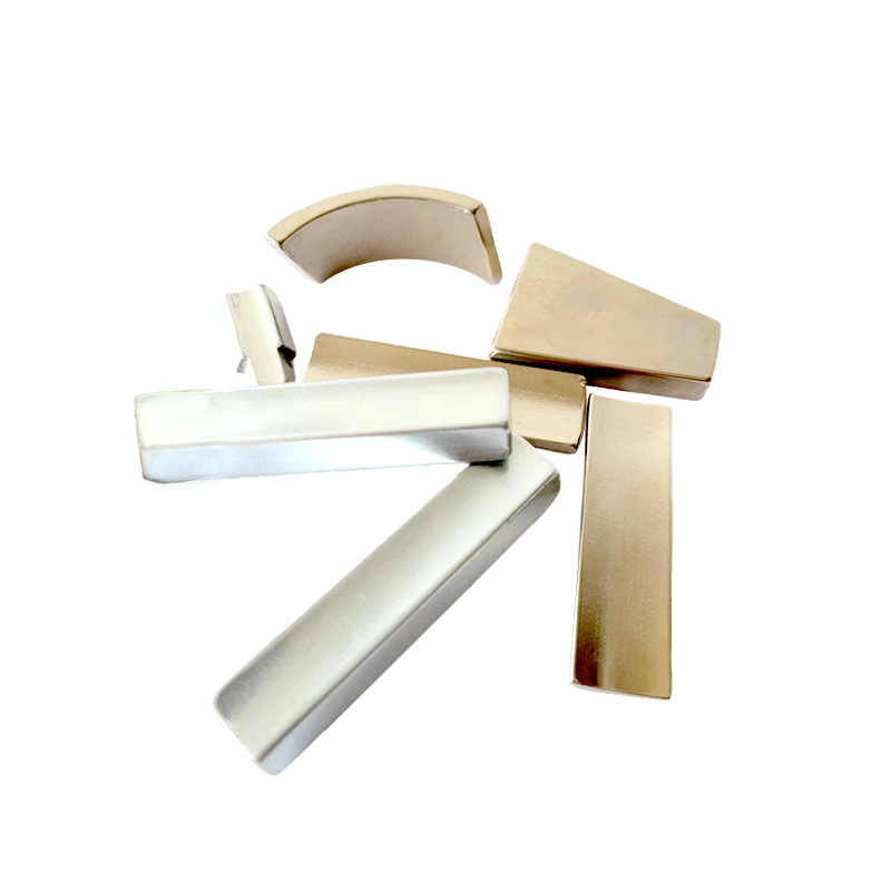
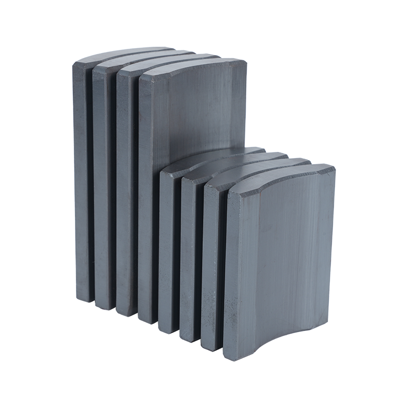
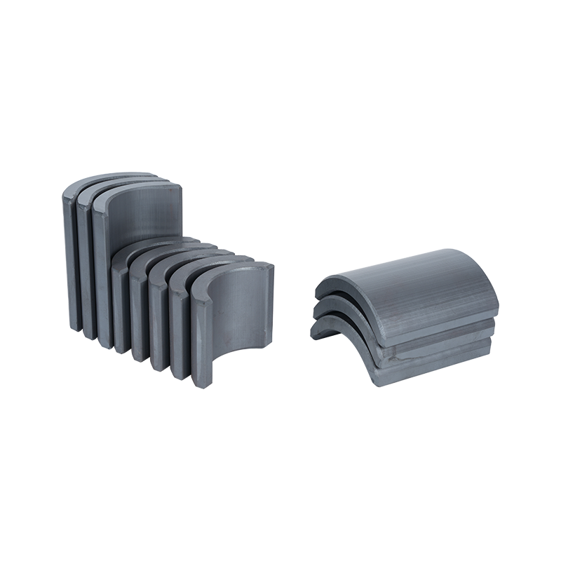
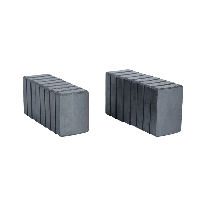
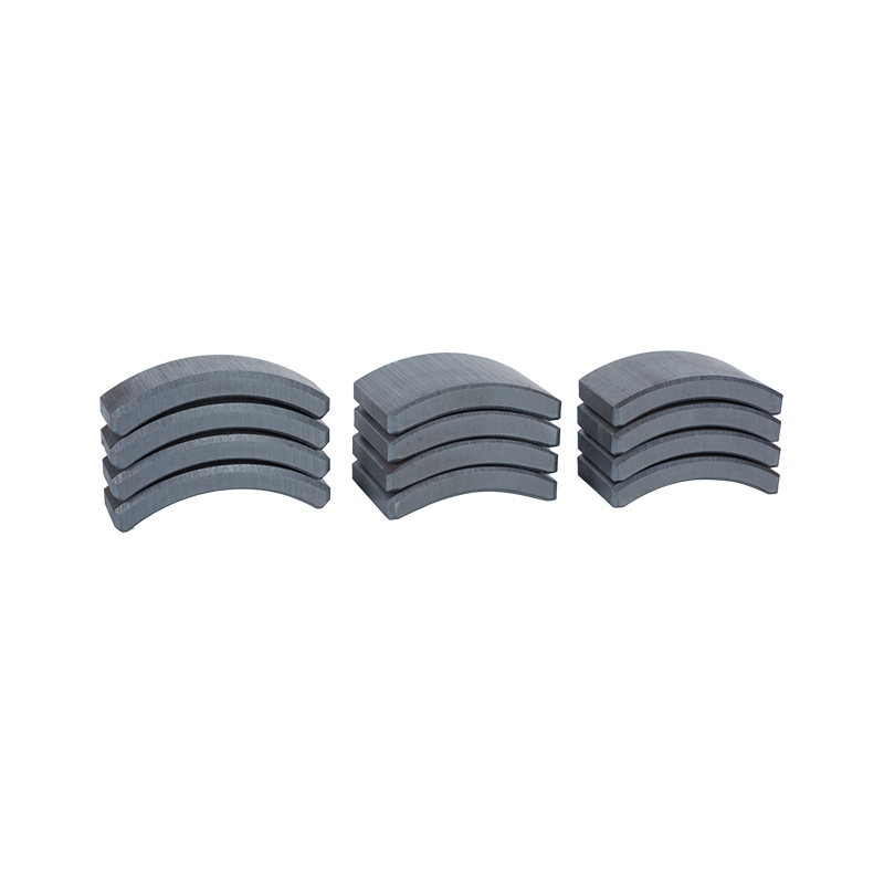
Dong Yang TianQi Magnetic Segment Co.,Ltd.(formerly Shuangyang Magnet Tile) is a professional enterprise specializing in the production of motor magnet tiles
Search by posts
Categories
Popular products
Contact Us
Industry News
 By Admin
Why Arc Segment Magnet Design Matters for Motor Performance
Every motor's job comes down to one thing: turning electrical energy into mechanical motion. The bridge between the two is a magnetic field, and how that field interacts with current‑carrying windings determines the torque a motor can deliver. It's easy to think of magnetism as a binary — present or absent — but in practice, the shape, strength, and distribution of that field are what separate a smooth‑running motor from one that vibrates, overheats, or underperforms.
Different applications pull the design in different directions. A motor built for high torque wants a strong, concentrated field. One built for smooth, quiet rotation wants consistency above raw strength. There's no universal "best" magnetic layout — only the layout that fits the job. And because these choices ripple through torque output, speed response, noise levels, heat buildup, and efficiency across the load range, they're worth getting right early. Retrofitting magnetic geometry after the mechanical design is locked in is a headache nobody enjoys.
Field Distribution: Where the Lines Actually Go
Inside a motor, magnetic field lines cross the air gap between rotor and stator, and it's this crossing that generates torque. How evenly those lines are spread — rather than just how many there are — has an outsized effect on performance.
A field concentrated in one region behaves very differently from one spread evenly around the circumference. When the distribution is uniform, the motor turns smoothly; when it's uneven, you get pulsing, vibration, or torque ripple that shows up as noise and wear over time. There's also an efficiency dimension: a field that lines up well with the winding layout converts more of the input energy into usable mechanical output, while a mismatch just bleeds energy away as heat.
Beyond torque and efficiency, field distribution shapes several other behaviors worth watching:
- Starting characteristics
- Speed regulation under changing conditions
- Response to sudden load changes
- Where and how heat tends to build up
Magnet Shape and Its Effect on Flux Path
If field distribution is the outcome, magnet geometry is often the cause. The physical shape of a magnet determines the path magnetic flux takes through the motor — where it concentrates, where it thins out, and how it meets the stator windings.
A flat magnet produces a fairly uniform field across its surface, which keeps the winding interaction simple. A curved magnet, by contrast, follows the natural curvature of the air gap, which tends to improve alignment and flux concentration. Segmented arcs go a step further, letting designers shape the field more deliberately by controlling how each piece contributes. Complex, custom profiles sit at the far end of this spectrum, built for applications where standard shapes just won't cut it.
| Magnet Shape | Field Characteristic | Motor Effect |
|---|---|---|
| Flat | Uniform field over flat surface | Simple winding interaction |
| Curved arc | Field follows curvature | Better air gap alignment |
| Segmented arc | Field distributed across multiple pieces | Controlled field shaping |
| Complex profile | Custom field distribution | Application‑specific tuning |
The right choice ultimately comes down to matching geometry to the motor's operating profile — there's no shape that wins across every use case.
Segmented vs. Single‑Piece Magnet Construction
One of the more consequential decisions in magnetic design is whether to build the field from several smaller magnet pieces or one continuous piece.
Segmented designs give engineers finer control. Because each piece can be positioned individually, the overall field can be tailored more precisely to the winding layout — useful when field shaping is a priority. The tradeoff is assembly complexity: more pieces mean more handling, more placement steps, and more opportunities for small errors to accumulate.
Single‑piece magnets go the other way. They're simpler to manufacture, easier to assemble, and their field is inherently consistent across the whole surface since there's no piece‑to‑piece variation to manage. The downside shows up later — if something fails or wears unevenly, the entire magnet needs replacing, whereas a segmented design lets you swap out individual pieces.
| Aspect | Segmented Design | Single‑Piece Design |
|---|---|---|
| Field shaping ability | Greater control | Limited by single geometry |
| Assembly complexity | More pieces to handle | Simpler assembly |
| Material utilization | Can use smaller pieces | Requires larger continuous piece |
| Field consistency | Depends on placement accuracy | Consistent across surface |
| Repair and replacement | Individual pieces replaceable | Entire magnet must be replaced |
Which approach wins usually comes down to whether the application values fine‑tuned field control or manufacturing simplicity more.
Placement: Small Errors, Real Consequences
Even a well‑shaped magnet underperforms if it's not positioned correctly. Placement determines exactly how the magnet's field interacts with the stator, and small deviations can have outsized effects.
A magnet positioned precisely produces even torque throughout a full rotation. Shift it slightly, and you introduce torque variation — the kind that shows up as roughness or vibration during operation. Alignment also governs how effectively the field and windings work together; even a well‑designed magnet loses much of its advantage if it's sitting a fraction of a millimeter out of place.
This matters just as much at the production level as it does in individual motor performance. Consistent placement across a manufacturing run means consistent behavior across units. Variable placement means every motor off the line performs a little differently — which is rarely what a manufacturer wants.
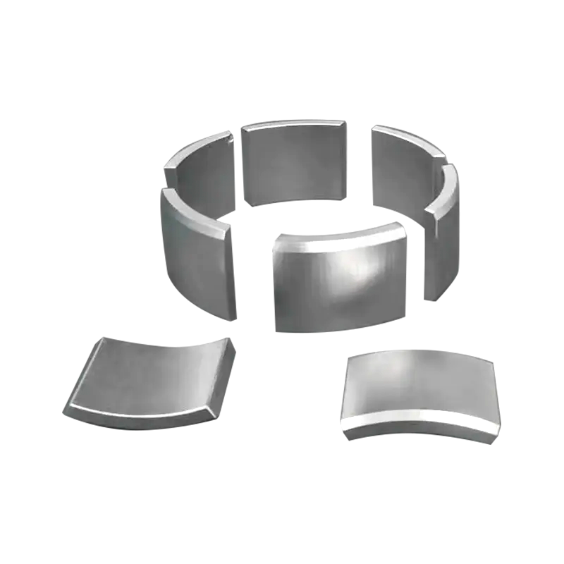
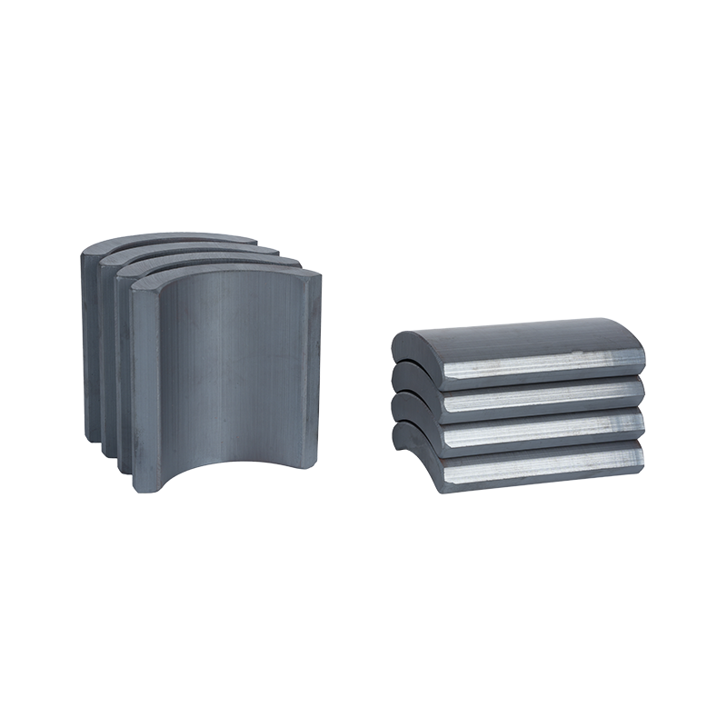
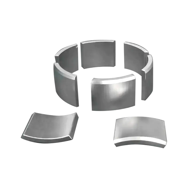
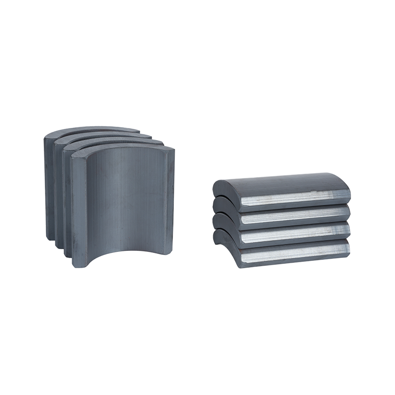
An Arc Segment Magnet mounted around the rotor illustrates this well. Its curvature needs to follow the intended path closely, matching the motor's geometry so the field lines up with the air gap as designed. Get that curvature and placement right, and the rest of the magnetic design has a much better chance of delivering on its intended performance.
Material Properties Connect to Shape and Performance
Not every magnetic material behaves the same way once you try to form it into a specific geometry. Some materials hold strong magnetic properties but resist certain shaping processes, while softer materials shape more readily but may not deliver the same field strength in return. That trade‑off shows up early in the design process, often before a final shape is even chosen.
Material selection also determines how much magnetic field a given piece of material can realistically produce. A compact piece made from one material might match the output of a much larger piece made from another. So the relationship between material and geometry isn't incidental — it defines what's physically achievable within a given footprint.
A few characteristics tend to separate one magnetic material from another:
- Field strength per unit of volume
- Behavior at elevated operating temperatures
- Resistance to gradual demagnetization over time
- Ease of machining or forming into complex shapes
An Arc Segment Magnet made from one material won't necessarily perform the same as an identical shape made from a different one. Matching material to application means weighing these characteristics against what the motor actually needs — a high‑heat environment calls for different priorities than a compact, room‑temperature application. Shape and material work as a pair here, not as separate decisions made in isolation.
How Segmented Magnet Construction Affects Assembly
Building a magnetic field from several smaller pieces introduces a different set of manufacturing demands than working with a single continuous magnet. Each segment has to be placed relative to its neighbors, and that additional handling naturally adds time and attention to the assembly line.
Precision during that placement step carries forward into final motor behavior. A small offset in one segment might seem minor on its own, but when several segments each drift slightly out of position, the combined effect can show up as a noticeable irregularity in the field — and eventually in how the motor runs.
Fixturing and reference marks help keep this under control. Holding each piece in a fixed position during placement, paired with clear alignment references, reduces the chance of small errors compounding across an assembly.
- How many segments make up the full assembly
- Handling requirements for each individual piece
- Fixturing needed to hold pieces in correct position
- Methods for checking placement after assembly
- Whether incorrect placement can be corrected or requires rework
A Segment Neodymium Magnet assembly involves placing each piece individually rather than dropping in one continuous ring.
How Field Consistency Relates to Motor Smoothness
Torque doesn't stay steady when the magnetic field feeding it isn't steady. Uneven field strength around the motor tends to translate directly into uneven torque, and that unevenness often shows up as pulsing or vibration during operation rather than smooth rotation.
A field that holds consistent strength around the full circumference tends to keep torque output steady in return, and steady torque generally means quieter, smoother running. The connection tends to follow a fairly direct chain: a more uniform field supports smoother rotation, smoother rotation reduces vibration, and reduced vibration lowers audible noise — all of which feeds into a more refined feel during operation.
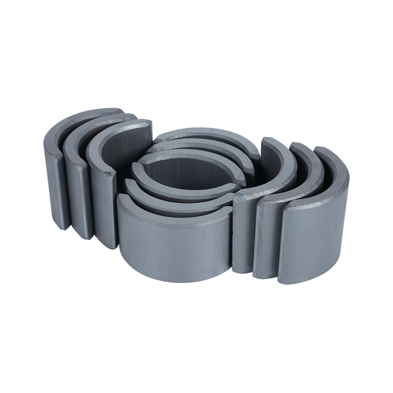
Getting there depends on both the shape of the magnet and how precisely it's positioned. A Motor Arc Magnet with even curvature along its length helps maintain that uniformity; any inconsistency in the curve itself tends to show up later as inconsistency in the field it produces.
How Motor Arc Magnet Designs Address Specific Applications
There isn't one arc magnet configuration that suits every motor. What works well for a slow‑turning, high‑torque application often looks quite different from what a fast‑spinning motor needs, because the field characteristics each one depends on aren't the same.
Requirements tend to shift depending on the job:
- High‑torque motors generally call for strong, concentrated fields
- High‑speed motors tend to benefit more from field consistency than raw strength
- Precision applications lean toward smooth, evenly distributed fields
- Compact motors need field strength to be used efficiently within limited space
The curvature of the arc itself plays into this. A tighter radius spreads the field across the air gap differently than a wider, shallower curve would, which is part of why arc geometry gets tuned rather than standardized across every motor type.
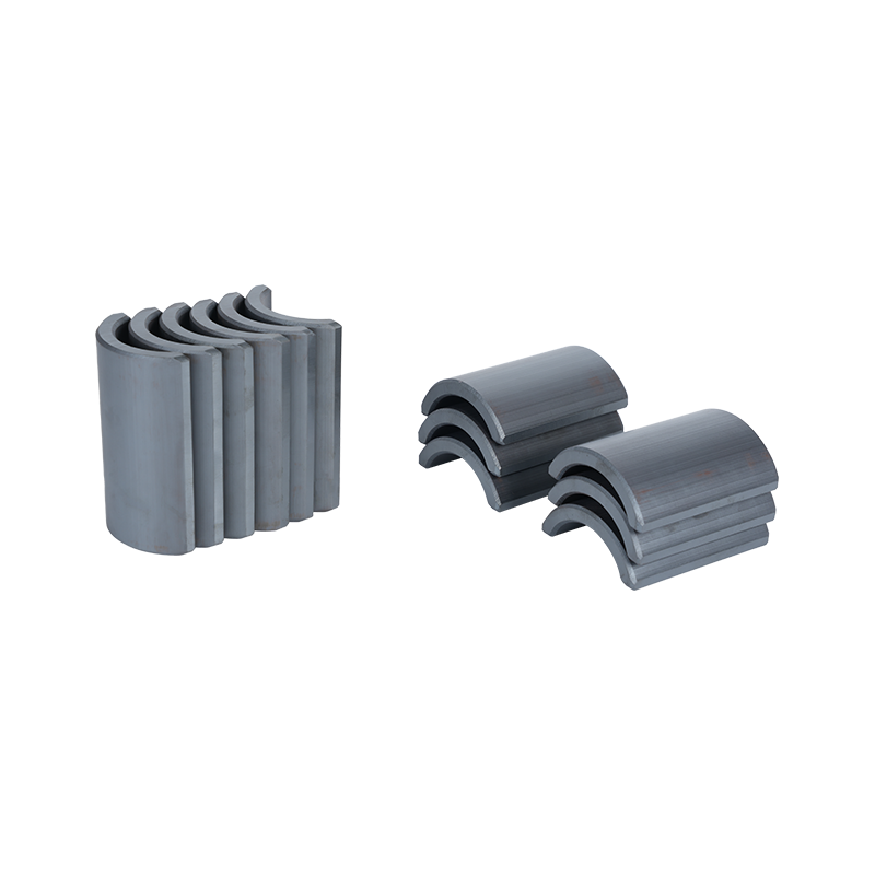
In practice, a Motor Arc Magnet built for a compact motor often looks and performs differently from one built for a larger frame size — the arc profile and the material behind it both get selected with the specific operating conditions in mind, rather than applied as a one‑size‑fits‑all solution.
What to Weigh When Evaluating Segmented Magnet Designs
Choosing a segmented magnet design usually comes down to balancing several factors at once rather than optimizing for just one.
Motor type and operating principle — different motor architectures place different demands on the magnetic field, so the design needs to align with how that particular motor is meant to run.
Required field distribution — the field needs to correspond with the winding layout and overall motor geometry, since this relationship drives both torque output and efficiency.
Assembly and manufacturing constraints — a design only works in practice if it can be assembled reliably, which means accounting for fixturing, handling time, and process complexity from the outset.
Material availability and cost — the chosen material needs to be sourceable in the quantities required, and it needs to fit within the constraints of the project budget.
Performance expectations — field strength, consistency, and thermal behavior all need to line up with what the application actually demands.
Consistency and repeatability — a design that performs well on paper still needs to hold up across repeated assembly runs, not just in a single prototype.
Application‑specific conditions — temperature range, rotational speed, and load variation each influence how a given magnet design behaves once it's in service.
| Consideration | What Gets Evaluated |
|---|---|
| Motor type | Field requirements tied to that specific motor architecture |
| Field distribution | Shape and placement needed for the desired field pattern |
| Assembly method | Fixturing, handling steps, and overall process flow |
| Material choice | Strength, thermal stability, and cost |
| Performance needs | Field strength alongside consistency |
| Consistency | Repeatability across a full production run |
Weighing these factors together — rather than picking one and treating the rest as secondary — tends to produce a design that holds up across both the bench test and the production floor.
Recommended products
-
Professional Customized Ferrite Motor Magnetic Tiles
-
Hard Segment Arc Ferrite Magnetic Tiles
-
Anti-Corrosion Ferrite Arc Magnetic Tiles
-
Strong Magnetic Permanent Ferrite Magnetic Tiles
-
Heavy Duty Sintered Ferrite Magnetic Tiles
-
Industrial Magnetic Tiles
-
Electric Motor Magnet Tiles
-
Curved Neodymium Magnet
-
Block Neodymium Magnet
Contact Us

Ever since its establishment, TIANQI has never stopped walking in pursuit of quality.
About Us
Products Links
Contact Information
-

NO.55, Jici Road, Hengdian Town, Dongyang City, Zhejiang Province, China
-

Tel: +86 579-6311101
+86 579-6311106 -

E-mail:[email protected]
Copyright © Dong Yang TianQi Magnetic Segment Co.,Ltd.
Magnetic Tiles Factory
