


 English
 中文简体
中文简体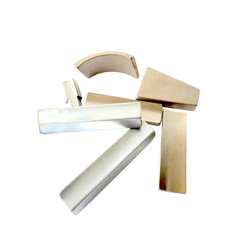
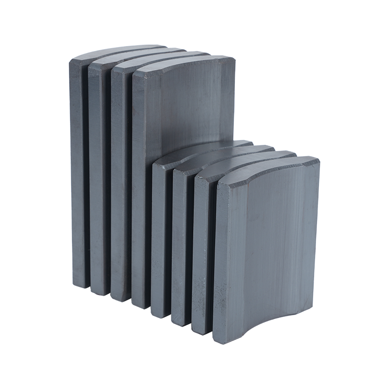
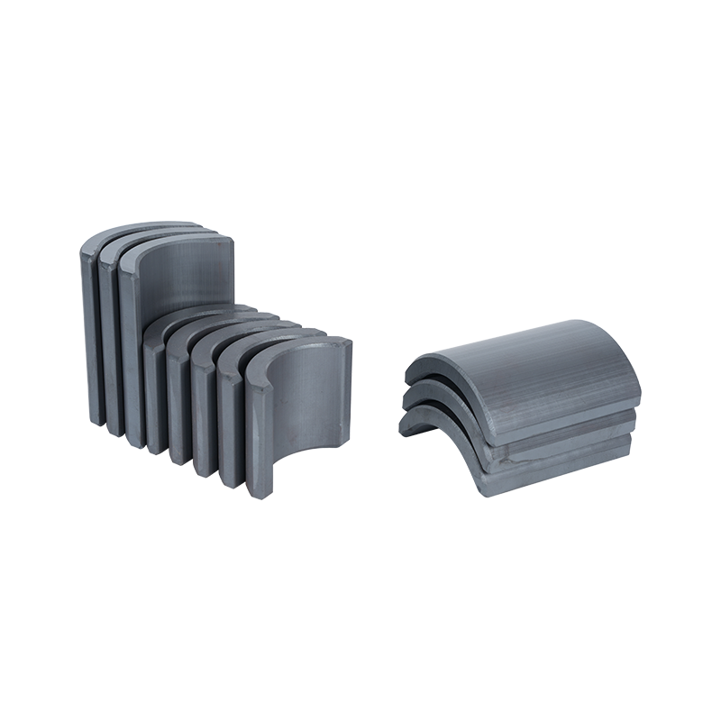
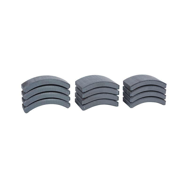
Dong Yang TianQi Magnetic Segment Co.,Ltd.(formerly Shuangyang Magnet Tile) is a professional enterprise specializing in the production of motor magnet tiles
Search by posts
Categories
Popular products
Contact Us
Industry News
 By Admin
What Factors Affect Curved Neodymium Magnet Performance
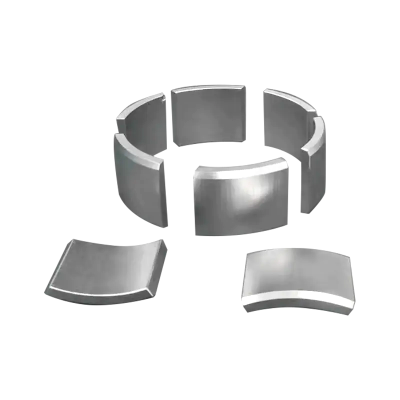
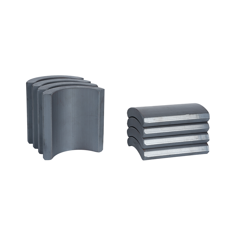
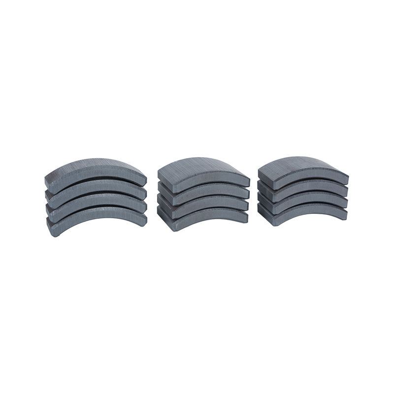
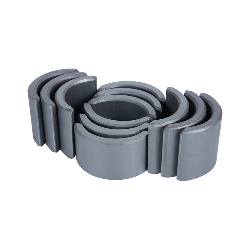
A curved magnet is shaped to follow the rounded surface found inside many rotating machines. Such geometry is not simply a change in appearance. Radius, arc length, thickness and mounting position all influence how the magnetic field interacts with nearby parts.
A Curved Neodymium Magnet usually sits along a circular rotor or stator surface, where a flat block would leave a less natural fit. Matching the magnet surface with the surrounding structure can help keep the magnetic path consistent around the curved assembly. Arc magnets are commonly considered together with the motor radius, pole arrangement and working air gap rather than as isolated components.
Shape also affects how much of the magnet surface faces the working area. A small change in curvature can alter the distance between different parts of the magnet and the nearby magnetic component. Such variation may influence how magnetic flux is distributed across the air gap.
For a motor using several curved pieces, consistency becomes important. Each segment needs to sit in a position that matches the intended circular arrangement. A difference in radius or mounting position can change the local magnetic conditions, even when the individual pieces appear similar.
Several geometry factors deserve attention:
- Inner and outer radius
- Arc angle
- Magnet thickness
- Axial length
- Surface fit
- Position around the rotor or stator
Geometry therefore needs to be considered alongside the complete motor structure. Choosing a magnet only by its physical size may overlook how the curved surface interacts with the surrounding magnetic circuit.
How Does the Air Gap Affect Magnetic Performance
Air gap refers to the space between the magnet and the nearby magnetic component. Within a motor, magnetic flux crosses that space, making its size and consistency important to the working condition of the magnet. Research on permanent magnet motors also links the air gap with the operating point of a permanent magnet.
For a curved design, maintaining a suitable gap around the arc can be more complicated than working with a flat surface. A magnet may have the correct radius on paper, yet its actual position during assembly can change the distance between surfaces.
A wider gap generally makes magnetic coupling weaker. An uneven gap can also cause different parts of the curved surface to experience different magnetic conditions. Such variation may affect the field pattern around the motor.
Assembly accuracy therefore has a direct connection with magnetic behavior. When a Motor Arc Magnet is installed around a circular structure, several factors should be checked together:
- Magnet curvature
- Mounting position
- Surface alignment
- Distance from the opposing component
- Spacing between neighboring segments
A stable air gap does not mean that every motor must use an identical gap. Actual requirements depend on the complete magnetic design. What matters is that the selected arrangement matches the intended operating conditions.
Changes in the air gap can also influence the magnet's operating point. Research into permanent magnet motors shows that changes in the magnetic circuit can shift the operating condition and may contribute to irreversible demagnetization under unsuitable circumstances.
For that reason, air‑gap control belongs to both magnetic design and mechanical assembly.
How Does Magnet Curvature Influence Flux Distribution
Magnetic flux does not simply travel through a magnet in one straight path. Its distribution depends on the magnet shape, surrounding materials and available magnetic path.
A curved surface can follow the circular air gap of a motor more closely than a rectangular block. Such a match helps create a more consistent relationship between the magnet face and the opposing surface. Arc geometry is commonly used in motor applications for that reason.
Curvature also changes the amount of magnetic material facing different parts of the working gap. A suitable arc allows the magnet to occupy the intended section of the circular path without forcing a flat piece into a curved space.
When the curve does not match the surrounding structure, several issues may appear:
- Uneven spacing across the magnet face
- Changes in local magnetic flux
- Greater variation between neighboring sections
- More difficult assembly
- Changes in motor operating behavior
Arc angle also matters. A small segment covers only part of the circular path, while a larger segment occupies a wider section. Several pieces may therefore be arranged around a rotor to create a repeated magnetic pattern.
The shape should not be judged separately from magnetization direction. A correctly curved magnet with an unsuitable magnetic orientation may still produce a field that does not match the intended motor arrangement.
How Does Magnet Material Affect Performance
Geometry tells only part of the story. Material characteristics determine how a magnet responds to its working environment.
Neodymium magnets are used in compact magnetic assemblies because they can provide substantial magnetic output from a relatively small volume. Different material grades, however, can respond differently to temperature and opposing magnetic fields. Selecting a material therefore involves more than choosing a convenient physical size.
For a Curved Neodymium Magnet, material selection should consider the actual working environment around the motor. Heat, magnetic load and mechanical arrangement can all influence how the magnet behaves during operation.
Magnetic properties also affect the amount of material needed for a particular design. A magnet with suitable magnetic characteristics may be designed differently from one with weaker magnetic behavior, even when both pieces have similar dimensions.
A practical selection process can consider:
| Factor | Why It Matters | Design Consideration |
|---|---|---|
| Magnetic Properties | Influence Available Magnetic Flux | Match the Motor Requirement |
| Material Grade | Affects Working Behavior | Consider Operating Conditions |
| Magnet Size | Influences Magnetic Circuit | Match Available Space |
| Curvature | Affects Surface Fit | Follow Motor Geometry |
| Coercive Behavior | Relates to Demagnetization Resistance | Consider Magnetic and Thermal Loads |
Material and shape should therefore be evaluated together. A curved magnet is part of a larger magnetic system, and its working behavior depends on how geometry, material and surrounding components interact.
How Does Temperature Change Curved Neodymium Magnet Performance
Heat is another factor that deserves attention in motor magnet selection. During operation, motors can generate heat around the rotor, stator and other internal components. A rise in magnet temperature can change its magnetic properties.
Research on NdFeB permanent magnets indicates that increasing temperature can reduce important magnetic characteristics, while unsuitable thermal conditions may increase the possibility of irreversible demagnetization.
For a Curved Neodymium Magnet, temperature needs to be considered across the actual operating environment rather than only during initial assembly. A magnet may perform normally under moderate conditions and behave differently as surrounding heat increases.
Heat can come from several sources:
- Motor electrical losses
- Friction within moving components
- Nearby heated parts
- Limited heat dissipation
- Repeated operation under demanding loads
Material selection can help address temperature‑related changes. Certain neodymium material families are designed for environments where greater thermal resistance is required, although the suitable choice depends on the actual motor design.
Temperature also interacts with the magnetic circuit. A magnet exposed to heat while facing an opposing magnetic field may experience a different working condition from a magnet operating under a lighter load.
For that reason, thermal review should take place alongside geometry and magnetic design. A curved shape may fit the rotor correctly, yet material selection still needs to account for the heat expected during operation.
How Does Magnetization Direction Affect a Motor Arc Magnet
Magnet shape and magnetization direction need to work together. A curved piece may fit neatly around a motor, yet its magnetic orientation still determines how the magnetic field interacts with nearby components.
For a Motor Arc Magnet, magnetization can follow different directions depending on the motor structure. Radial, parallel and other arrangements can create different field patterns, so orientation needs to match the intended magnetic path rather than being selected only from the outside shape.
When several arc magnets are placed around a rotating assembly, their poles need to follow the planned sequence. An incorrect orientation can disturb the expected field arrangement and change motor behavior.
During assembly, simple checks can help prevent avoidable mistakes:
- Mark the intended pole direction before installation
- Keep neighboring magnets in their planned orientation
- Check the position of each curved piece against the assembly drawing
- Avoid assuming that similar‑looking magnets have the same magnetic direction
- Inspect the complete arrangement after installation
Magnetization direction can also affect torque and other operating characteristics in permanent magnet motors. Research into arc‑shaped magnets and motor arrangements shows that magnet orientation is closely connected with magnetic field distribution and motor performance.
For production and assembly work, orientation marks can therefore be just as useful as dimensional inspection. A magnet that has the correct radius and thickness may still need to be rejected from a particular position when its magnetic direction does not match the intended arrangement.
How Do Manufacturing Tolerances Affect Curved Magnet Performance
A curved magnet has several dimensions that need to work together. Radius, arc length, thickness and width can all affect how a piece fits inside a circular motor structure.
Small dimensional differences may become noticeable when several pieces are arranged around one assembly. A slight difference in radius can change how closely a magnet follows the surrounding surface, while a variation in thickness can influence the working air gap.
Consistency also matters at the joints between neighboring magnets. Uneven spacing can create changes in the magnetic field around the circumference. Mechanical positioning and magnetic behavior are therefore connected.
Inspection can focus on practical points rather than looking only at one dimension:
- Shape: Check whether the curved surface matches the intended mounting area.
- Thickness: Check whether the magnet creates the expected spacing after installation.
- Arc length: Make sure neighboring pieces fit within the planned circular arrangement.
- Edge condition: Inspect edges for damage that could affect seating or installation.
- Position: Check whether each piece sits in its assigned location.
Manufacturing consistency becomes particularly relevant when a motor contains several similar curved pieces. Repeated shapes need to fit together as a group, so variation in one component can influence the overall assembly.
A Curved Neodymium Magnet should therefore be inspected as both an individual component and part of a circular set. Good dimensional control helps reduce unwanted changes in spacing and makes assembly more predictable.
How Do Installation Conditions Influence Final Performance
Installation is where geometry, material and magnetic orientation come together. Even a suitable magnet can behave differently when it is positioned incorrectly or mounted against an unsuitable surface.
A curved magnet needs close contact with its intended mounting area. An unwanted gap between the magnet and mounting surface can change its position relative to the air gap. Adhesive thickness can also affect the final position, especially when several magnets are installed around a circular structure.
Mechanical alignment deserves similar attention. A magnet that sits slightly out of position can change the distance between its working face and the opposing component. Such a change may seem small during assembly while still affecting the magnetic conditions inside the motor.
During installation, several points can be checked:
- Confirm the curved surface matches the mounting area
- Keep each magnet in its assigned position
- Check the intended pole direction
- Inspect spacing between neighboring magnets
- Keep unwanted material away from the working air gap
- Allow mounting materials to settle according to their required process
- Inspect the complete circular arrangement before operation
Mechanical stress also deserves care. Neodymium magnets are relatively brittle compared with many common metals, so impact or excessive force can cause chips or cracks. Damaged edges may affect seating and can make later assembly less predictable.
Environmental conditions matter after installation as well. Heat around a motor can influence magnetic properties, while moisture or unsuitable surrounding materials may affect the mounting environment. A suitable protective treatment may be considered where the working conditions require additional surface protection.
Looking at installation as part of the magnetic design helps avoid a common mistake: treating the magnet as an independent component after it has been selected. Its actual position, orientation and surrounding materials determine how it participates in the complete motor.
Why Should Magnet Performance Be Checked Within the Complete Motor
A Curved Neodymium Magnet does not work alone. Its behavior depends on the relationship between geometry, material, air gap, magnetization direction and nearby motor components.
For that reason, checking only the magnet before installation cannot provide a complete picture. A magnet may meet its intended dimensional requirements while the assembled motor still shows unexpected behavior because of positioning, spacing or thermal conditions.
A practical review can follow the path of the component through production:
Material Selection → Shape Inspection → Magnetization Check → Assembly Position → Air Gap Check → Thermal Review → Motor Testing
Each stage answers a different question. Material selection concerns magnetic and thermal behavior. Shape inspection confirms physical fit. Magnetization checks verify pole direction. Assembly inspection confirms position and spacing. Thermal review considers operating conditions.
Such a process also makes troubleshooting easier. When motor behavior changes, engineers can compare current conditions with earlier inspection results instead of changing several variables at once.
For a Motor Arc Magnet, the curved shape is only one part of performance. A suitable radius cannot compensate for incorrect magnetization, and a suitable material cannot correct poor installation alignment. Air‑gap changes can also influence magnetic behavior even when the magnet itself remains unchanged.
A complete view of the motor gives a clearer basis for selecting and installing curved magnets. Geometry, magnetic properties, heat and assembly conditions need to remain compatible throughout the working process.
Recommended products
-
Professional Customized Ferrite Motor Magnetic Tiles
-
Hard Segment Arc Ferrite Magnetic Tiles
-
Anti-Corrosion Ferrite Arc Magnetic Tiles
-
Strong Magnetic Permanent Ferrite Magnetic Tiles
-
Heavy Duty Sintered Ferrite Magnetic Tiles
-
Industrial Magnetic Tiles
-
Electric Motor Magnet Tiles
-
Curved Neodymium Magnet
-
Block Neodymium Magnet
Contact Us

Ever since its establishment, TIANQI has never stopped walking in pursuit of quality.
About Us
Products Links
Contact Information
-

NO.55, Jici Road, Hengdian Town, Dongyang City, Zhejiang Province, China
-

Tel: +86 579-6311101
+86 579-6311106 -

E-mail:[email protected]
Copyright © Dong Yang TianQi Magnetic Segment Co.,Ltd.
Magnetic Tiles Factory
