


 English
 中文简体
中文简体
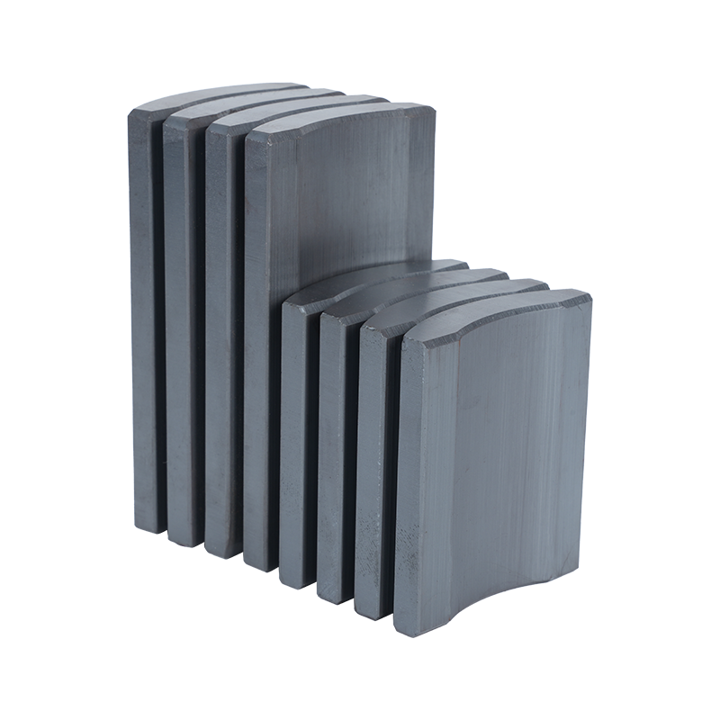
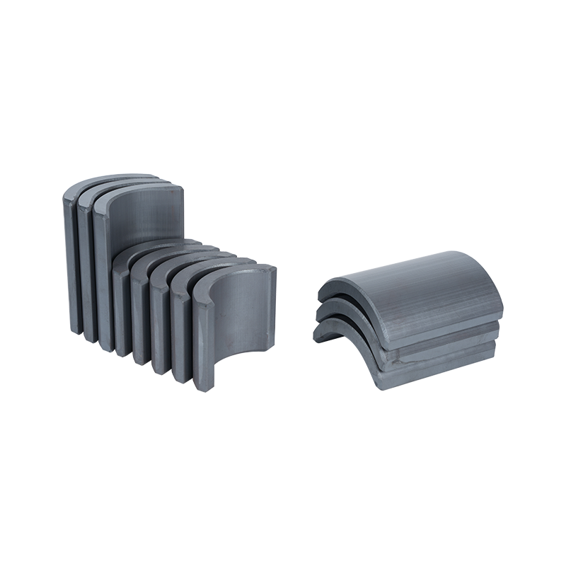
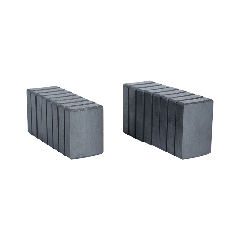
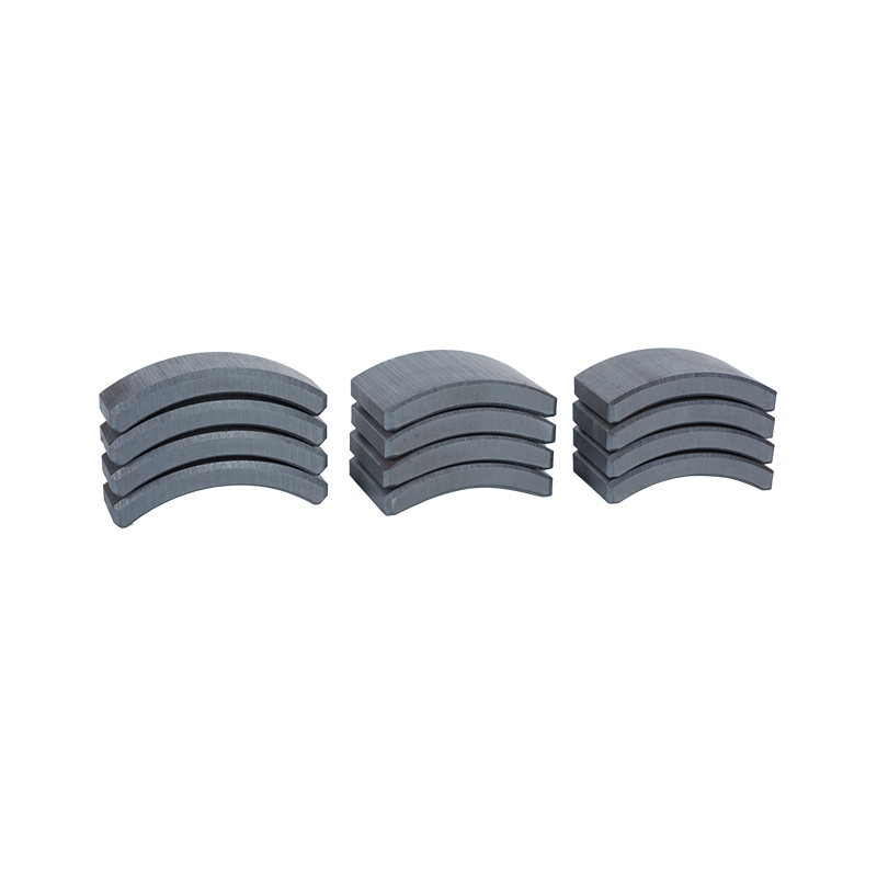
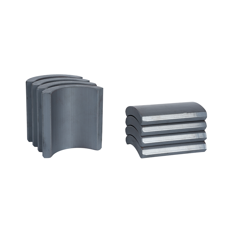
Dong Yang TianQi Magnetic Segment Co.,Ltd.(formerly Shuangyang Magnet Tile) is a professional enterprise specializing in the production of motor magnet tiles
Search by posts
Categories
Popular products
Contact Us
Industry News
 By Admin
How Does Rotor Design Affect Ferrite Magnet Selection
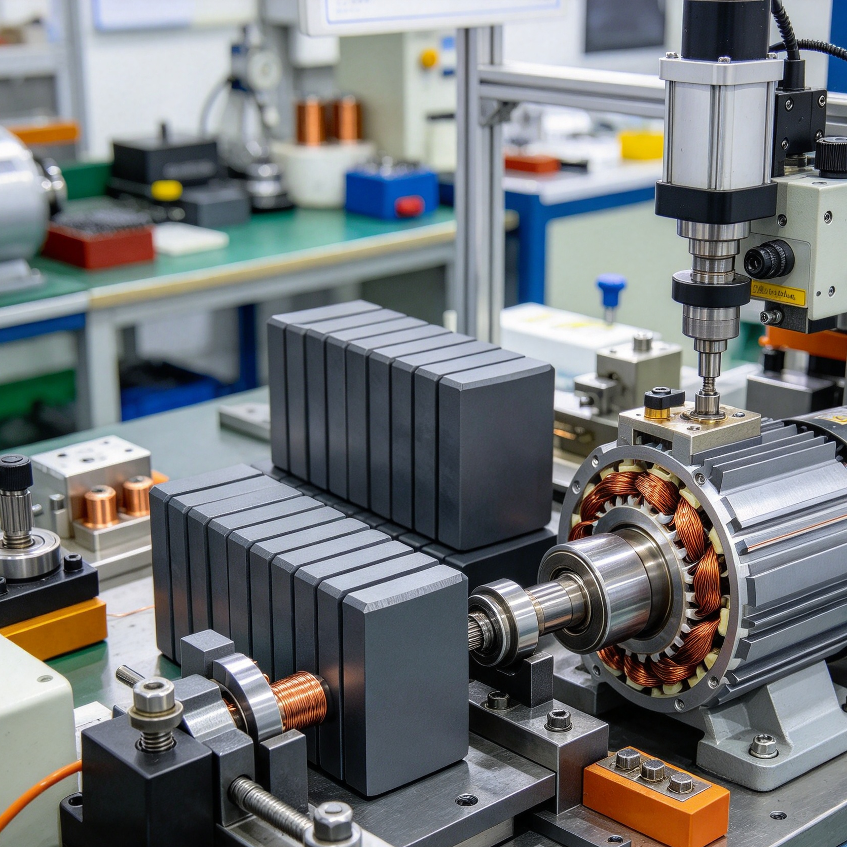
A motor rotor may look like a simple rotating component, but its internal structure has a direct influence on how magnets need to get selected and positioned within it. The shape of the rotor, the location of the magnets, the available space, and the intended magnetic path all affect how the finished motor works as a complete system together.
This is why choosing a Ferrite Magnet for Motor shouldn't get treated as a separate material decision made in isolation. The magnet needs fitting the rotor structure and working with the surrounding motor components as one assembly. A suitable choice depends not only on the magnet itself, but also on how the rotor holds it and how the magnetic field moves through the motor.
For manufacturers and buyers, this creates a genuinely more practical way to approach magnet selection. Instead of asking which magnet can get used in a motor, it proves useful asking how the rotor is designed and what the magnet needs doing within that structure.
Why Does Rotor Structure Matter When Selecting Ferrite Magnets?
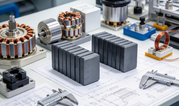
The rotor provides the physical space where magnets get placed and supported throughout operation. Its shape determines how much room stays available, how the magnets get arranged, and how the magnetic field interacts with the surrounding parts nearby.
A rotor with magnets mounted on its outer surface creates a genuinely different design situation from one with magnets placed inside the rotor body itself. The mounting position changes the relationship between the magnet, rotor material, air gap, and stationary motor components sitting close by.
| Rotor Consideration | Effect on Magnet Selection |
|---|---|
| Available mounting space | Influences magnet shape and placement |
| Rotor surface shape | Affects how magnets can be attached |
| Internal cavities | Create different mounting possibilities |
| Magnet orientation | Changes the magnetic field arrangement |
| Rotor support structure | Influences mechanical stability |
The magnet therefore needs considering as part of the rotor assembly, rather than as an isolated component sitting apart from it. This approach can also help reduce unnecessary design changes later in production down the line. When the rotor structure and magnet arrangement get considered together, manufacturers can make genuinely more practical choices during product development.
How Does Magnet Mounting Location Change the Design?
Magnet mounting location has a genuinely direct relationship with rotor construction throughout the design process. Magnets can get positioned on the rotor surface, within openings, or in other locations created by the rotor structure itself.
Surface-mounted magnets sit directly exposed toward the air gap facing the stationary parts. This arrangement can make the magnet position relatively easy to understand from a manufacturing perspective on the floor. It can also create specific requirements for attachment and protection against wear.
Magnets placed within the rotor create a genuinely different structure entirely. The surrounding rotor material can influence the magnetic path and provide physical support around the magnet itself.
The choice between these arrangements depends on the motor design overall.
| Mounting Location | Design Focus |
|---|---|
| Rotor surface | Attachment and outer profile |
| Internal position | Rotor structure and magnetic path |
| Recessed area | Magnet fit and retention |
| Segmented location | Consistent spacing and orientation |
A magnet shape that fits one mounting position may not suit another rotor entirely. This is why the rotor layout needs considering before finalizing the magnet form for production.
What Role Does Rotor Shape Play in Magnet Shape?
Rotor geometry can influence the physical shape of the magnet considerably during design. A flat rotor surface may allow a relatively simple magnet shape, while a curved or segmented surface may require a genuinely different form instead.
The goal isn't simply filling the available space without regard for function. The magnet needs sitting in a position that supports the intended magnetic arrangement without creating unnecessary gaps or assembly difficulties down the line.
Common design considerations include the contact between the magnet and rotor, the available mounting area, and the magnet orientation relative to neighboring components. Space between neighboring magnets matters too, along with rotor surface shape and the assembly method planned for production.
These factors can influence whether a rectangular, curved, segmented, or custom-shaped ferrite magnet proves practical for the job. A Ferrite Magnet for Motor therefore needs considering alongside the physical structure surrounding it in the rotor. The magnet dimensions and shape should follow the needs of the rotor, rather than getting selected independently of it.
How Does Magnet Layout Affect Rotor Performance?
Magnet layout describes how individual magnets get distributed around the rotor's circumference. Their position and orientation determine how the magnetic field gets organized as the rotor turns during operation.
Even spacing can help create a predictable arrangement around the rotor as it spins. However, the exact layout depends on the motor structure and the intended operating behavior expected from it.
A rotor may use several individual magnets positioned around its circumference at regular intervals. Another design may use longer magnet sections or a genuinely different arrangement within the rotor body instead.
| Layout Feature | Practical Design Concern |
|---|---|
| Magnet spacing | Consistent rotor arrangement |
| Magnet orientation | Direction of magnetic field |
| Magnet quantity | Available rotor space |
| Segment shape | Assembly compatibility |
| Pole arrangement | Relationship with surrounding motor parts |
The magnet layout should also consider how the rotor gets manufactured and assembled on the production line. A layout that looks suitable in a drawing may become genuinely difficult to produce if the magnet positions prove difficult accessing or maintaining consistently across units. This makes layout planning important for both magnetic behavior and manufacturing practicality together.
How Does the Magnetic Circuit Influence Ferrite Magnet Selection?
The magnetic circuit describes the path followed by the magnetic field through the motor structure as a whole. Rotor materials, magnet position, air gaps, and nearby components all influence this path considerably.
Ferrite magnets have specific magnetic characteristics that need working with the surrounding motor design already in place. If the rotor structure doesn't provide a suitable path, simply changing the magnet size may not solve the underlying design issue at hand.
Manufacturers can therefore examine the complete magnetic route, rather than looking at the magnet alone in isolation. A useful design review can trace where the magnetic field leaves the magnet, how it passes through the rotor structure, and where it crosses the air gap toward the stationary section. From there, tracking how the field interacts with the stationary motor part and returns through the surrounding structure completes the picture.
This system-level view can make magnet selection genuinely more logical for the engineering team. The purpose is matching the magnet with the path created by the motor, rather than treating magnetic performance as an isolated feature on a spec sheet.
Can Rotor Material Affect Magnet Selection?
The material used in the rotor can influence how the magnetic field behaves around the magnet sitting within it. Different rotor structures may provide genuinely different paths for the magnetic field to follow.
This matters when deciding where the magnet should get placed and how much surrounding material should remain around it. A rotor can get designed to support the magnet mechanically while also forming part of the magnetic path itself. These two functions need working together throughout the design.
| Rotor Material Consideration | Design Question |
|---|---|
| Magnetic behavior | How does the material affect field movement? |
| Structural support | Can it hold the magnet securely? |
| Surface condition | Does it support practical mounting? |
| Manufacturing method | Can the required magnet position be produced? |
The magnet and rotor material should therefore get reviewed as a combined system, rather than separately. This can also help manufacturers avoid selecting a magnet based only on its standalone properties listed on a datasheet.
Why Does the Air Gap Matter to Rotor and Magnet Design?
The space between the rotating and stationary parts of a motor affects the relationship between the magnet and the rest of the magnetic system considerably. A smaller or larger air gap can change how effectively the magnetic field crosses the space between components as the rotor spins.
Rotor shape and manufacturing consistency therefore become genuinely important when magnets sit positioned close to the motor's stationary section nearby. The magnet itself is only one part of this broader relationship worth considering.
The rotor must maintain a suitable position during rotation, while the surrounding structure needs providing enough space for safe operation throughout the motor's life. This makes rotor assembly and magnet placement closely connected in practice. A practical design review may consider rotor alignment alongside magnet position, surface shape, assembly consistency, and the space between rotating and stationary parts. These factors can influence how a ferrite magnet should get shaped and mounted for the application.
How Does Rotor Assembly Affect Magnet Retention?
A rotating magnet needs remaining securely positioned during normal motor operation throughout its working life. This creates a mechanical requirement in addition to the magnetic requirement already discussed.
The attachment method depends on the rotor structure and magnet location within it. Some designs may rely on a suitable bonding method, while other structures can provide physical support around the magnet directly. The choice should consider how the magnet interacts with the rotor during both assembly and operation over time.
Magnet retention can involve adhesive bonding, recessed mounting, mechanical support built into the rotor, or a combination of these methods together. The attachment area should also stay compatible with the magnet's surface and the rotor material surrounding it. If the mounting method proves difficult controlling during production, it may affect consistency between finished motor assemblies coming off the line.
How Can Rotor Segmentation Influence Magnet Arrangement?
Some rotors use separate sections, rather than one continuous body running through the design. This can create additional options for magnet placement within the structure.
Segmented structures may allow magnets getting positioned in clearly defined locations across the rotor. They can also make certain assembly processes genuinely easier when the motor requires multiple magnetic sections around the rotor's circumference. At the same time, segmentation creates more interfaces that need remaining consistent throughout production.
| Segmented Rotor Area | Relevant Consideration |
|---|---|
| Magnet seat | Correct physical fit |
| Segment connection | Structural stability |
| Magnet spacing | Consistent magnetic layout |
| Rotor alignment | Smooth assembly |
| Assembly access | Practical production process |
The magnet design should follow the structure of the rotor segments closely. This proves especially relevant when manufacturers need producing repeated assemblies with genuinely similar magnetic layouts across a batch.
How Does Rotor Speed Influence Magnet Mounting Decisions?
Rotor speed can affect the mechanical demands placed on magnets and their mounting systems throughout continuous operation. As the rotor moves, magnets face exposure to continuous rotational forces pulling against their mounting.
This means magnet retention can't get considered separately from the rotor structure supporting it. A magnet that fits into a rotor cavity still needs suitable support during operation over time. Surface-mounted arrangements may require particular attention to attachment because the magnet sits closer to the outer rotor surface facing the air gap.
The design team can therefore consider both the magnetic function and the mechanical environment together. A practical selection process may review magnet position, rotor shape, attachment method, and the support surrounding the magnet, along with assembly consistency across the production run. The aim is creating a rotor where the magnet remains properly positioned throughout normal operation for the life of the motor.
What Should Manufacturers Consider When Matching Magnets With Rotor Design?
Manufacturers need looking beyond magnet material when developing a motor rotor from scratch. The physical relationship between the magnet and rotor should get reviewed during product development from the earliest stages.
This includes the mounting location, magnet shape, orientation, support structure, and surrounding magnetic path all working together. A useful matching process can get organized around several practical questions worth asking early. Where will the magnet get positioned, and what shape fits the rotor available? How will the magnet get secured, and how will the magnetic field move through the rotor structure?
Additional questions cover how neighboring magnets will get arranged and how the rotor will get assembled on the line. Whether the design can get produced consistently across a production run matters just as much. These questions help connect magnet selection with actual motor construction on the factory floor. For buyers, they also provide a genuinely useful framework when discussing custom magnet requirements with manufacturers directly.
How Can Custom Ferrite Magnets Fit Different Rotor Structures?
Not every rotor has the same shape or magnet mounting arrangement across different motor designs. Custom ferrite magnets may therefore get considered when standard shapes don't fit the intended structure properly.
Customization can involve the physical form, mounting position, orientation, or arrangement of the magnet within the rotor. However, customization should begin with the rotor design, rather than the magnet alone sitting apart from it. A manufacturer may need reviewing drawings, mounting areas, assembly methods, and the intended magnetic layout before recommending a suitable form for production.
| Customization Area | Rotor-Related Purpose |
|---|---|
| Magnet shape | Fits the available rotor space |
| Magnet orientation | Supports the planned magnetic layout |
| Surface form | Matches the rotor profile |
| Segment design | Supports repeated placement |
| Mounting features | Works with the assembly method |
This approach can help keeping the magnet closely connected with the actual motor structure it serves. It also reduces the risk of creating a magnet shape that looks suitable on paper but creates difficulties during assembly on the floor.
How Does Production Consistency Affect Rotor Magnet Selection?
Rotor design needs working, not only in a drawing, but also during repeated production runs over time. Small differences in magnet placement, rotor alignment, or assembly can change the relationship between components across a batch.
A practical design therefore needs considering how easily each part can get positioned consistently by the production team. Magnet selection can support this process when the magnet shape and mounting method stay suitable for the production environment already in place. Manufacturers can inspect areas such as magnet position, rotor alignment, and magnet orientation alongside mounting condition, surface contact, and overall assembly appearance.
These checks can help identify issues before the motor moves into later production stages further down the line. For B2B buyers, production consistency is also a genuinely important consideration when comparing suppliers side by side. The discussion should include not only the magnet material but also how the supplier handles shapes, layouts, packaging, and production requirements across an order.
What Should Buyers Ask About a Ferrite Magnet for Motor?
A buyer evaluating ferrite magnets for a motor can gain genuinely useful information by discussing the rotor structure directly with the supplier. Instead of asking only about the magnet material, buyers can describe where the magnet will get installed and how the rotor is constructed already.
Useful questions include what magnet shape fits the rotor location and how the magnet should get oriented within it. Buyers can also ask what mounting method suits the rotor structure and whether the magnet layout matches the intended magnetic path planned for the motor. Whether the magnet form can get adjusted for the rotor matters too, along with how the finished magnets should get handled during assembly on the line.
These questions encourage a genuinely more complete discussion between the buyer and manufacturer working together. They also help ensuring the selected magnet gets considered within the actual motor structure it's meant to serve.
How Can Rotor Design Guide Better Magnet Selection?
Rotor design provides a practical starting point for understanding magnet requirements from the outset. The rotor determines where magnets can get placed, how they can get supported, and how the magnetic field can interact with the surrounding motor structure around it.
Magnet selection can then follow those physical and functional needs already established by the design. For manufacturers, this means reviewing rotor geometry, magnet mounting locations, magnet layout, rotor materials, magnetic paths, air gaps, and assembly methods as connected design elements working together.
For buyers, the same approach can make sourcing discussions more precise from the initial conversation. A clear description of the rotor structure can help a supplier understand what type of ferrite magnet is being considered and where it needs to fit within the assembly. The result is a more connected development process in which the rotor and magnet are designed to work together rather than being treated as separate components.
Recommended products
-
Professional Customized Ferrite Motor Magnetic Tiles
-
Hard Segment Arc Ferrite Magnetic Tiles
-
Anti-Corrosion Ferrite Arc Magnetic Tiles
-
Strong Magnetic Permanent Ferrite Magnetic Tiles
-
Heavy Duty Sintered Ferrite Magnetic Tiles
-
Industrial Magnetic Tiles
-
Electric Motor Magnet Tiles
-
Curved Neodymium Magnet
-
Block Neodymium Magnet
Contact Us

Ever since its establishment, TIANQI has never stopped walking in pursuit of quality.
About Us
Products Links
Contact Information
-

NO.55, Jici Road, Hengdian Town, Dongyang City, Zhejiang Province, China
-

Tel: +86 579-6311101
+86 579-6311106 -

E-mail:[email protected]
Copyright © Dong Yang TianQi Magnetic Segment Co.,Ltd.
Magnetic Tiles Factory
