


 English
 中文简体
中文简体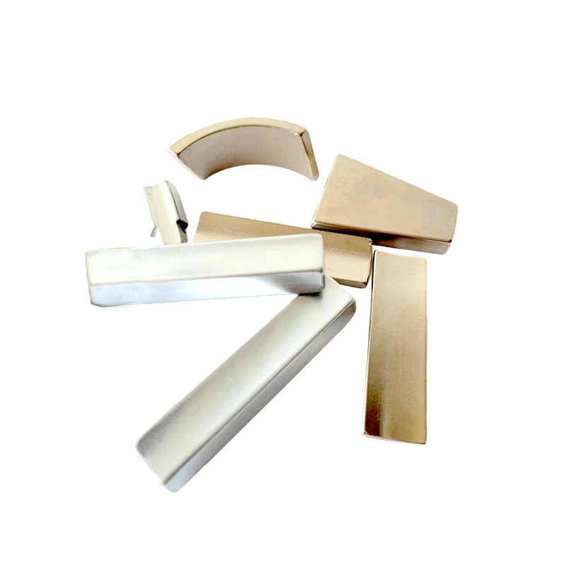
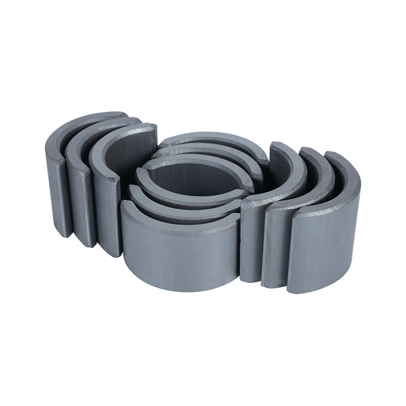
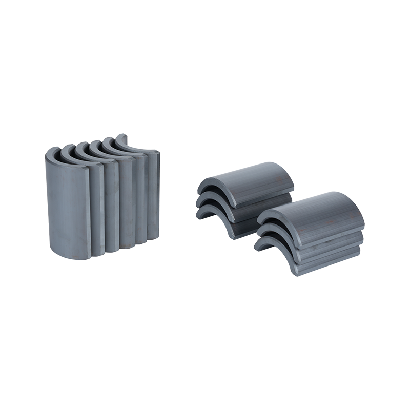
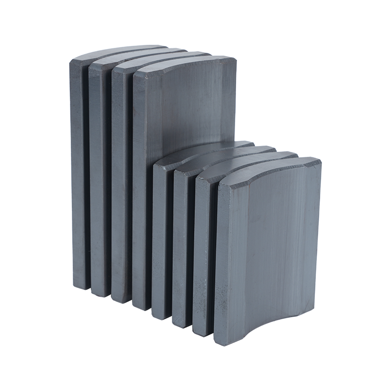
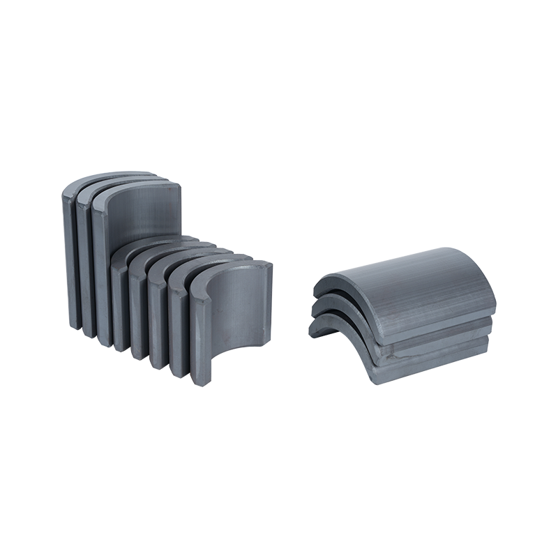
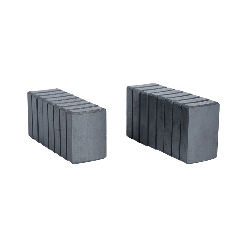
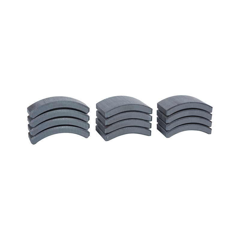
Dong Yang TianQi Magnetic Segment Co.,Ltd.(formerly Shuangyang Magnet Tile) is a professional enterprise specializing in the production of motor magnet tiles
Search by posts
Categories
Popular products
Contact Us

Industry News
 By Admin
How Does Motor Arc Magnet Support Electric Motor Design Needs
An electric motor packs several parts into a tight, mostly circular space. A magnetic piece sitting inside that structure has to match the available room without leaving gaps or bumping into anything else. Shape turns into a real engineering question here, not just a detail that looks a certain way on paper.
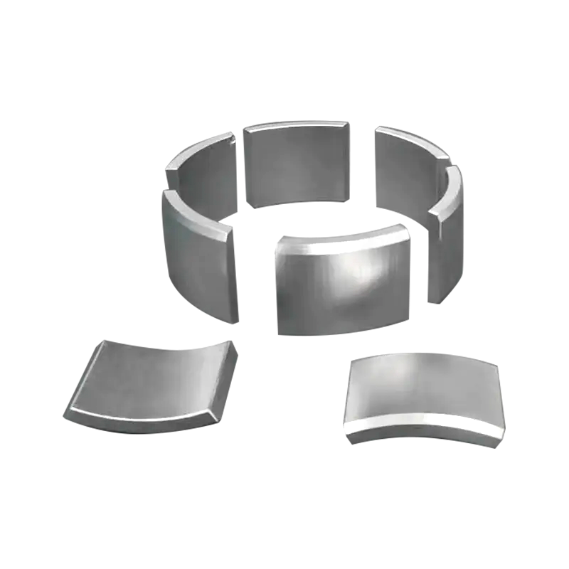
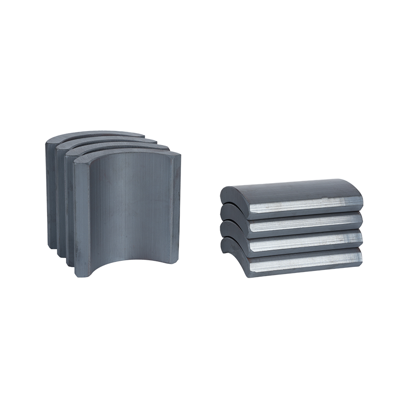
A Motor Arc Magnet carries a curved body that follows the round shape inside a motor housing. Several of these pieces can line up along a circular path, building a connected magnetic ring around a rotor or another section built for it. A flat piece dropped into that same curved space would leave awkward gaps behind it, something an arc-shaped piece avoids by hugging the contour instead.
Motor size, the clearance inside, where the magnet sits, and whatever parts surround it all push and pull on what shape actually works. Adjust one dimension and something else shifts too. Make the magnet thicker, and the gap to nearby components shrinks. Change the arc length, and the spacing between neighboring pieces changes right along with it.
Shape also has to match how the motor actually runs. A spinning rotor needs room to move freely, while the magnetic pieces need to stay locked in their spots. Getting the geometry right keeps that relationship steady once the motor is running under real conditions, not just sitting on a workbench.
A few design points tend to show up together in this kind of work:
- Curvature of the installation surface
- Available radial and axial space
- Magnet length and width
- Position of nearby motor components
- Arrangement of several magnetic pieces
- Required clearance during movement
A magnetic part gets designed alongside the motor structure, not separately from it. Shape, position, and available space end up as one connected decision rather than three separate ones made on their own schedule.
How Does a Motor Arc Magnet Fit the Curved Motor Structure?
A circular motor naturally calls for curved parts. A magnet wrapped around a rotor or fitted inside a housing has to trace that surrounding contour closely, otherwise it drifts out of position over time. Curvature and installation go hand in hand here.
An arc-shaped magnet typically has two curved faces, one on the inside and one on the outside. Depending on how the motor is built, one face might sit right up against the rotor or some other internal part, while the other faces outward toward the surrounding housing. Getting those two surfaces to match the intended installation spot cuts down on gaps nobody wants.
Curvature also decides how well several pieces sit side by side. A set of magnetic segments can trace a circular path, each one taking up its own slice of the circumference. Uneven curvature throws off the spacing between neighbors, which makes assembly harder and messes with the layout everyone planned for.
Clearance needs its own attention too. A magnet can't just be shaped to match a curve without thinking about the moving parts nearby. There has to be enough room left for assembly and for movement, but too much space changes the relationship between the magnet and the structure around it in ways that aren't always obvious until the motor is running.
| Design Area | Main Question |
| Inner Curve | Does the magnet follow the intended internal surface? |
| Outer Curve | Does the outside surface match the surrounding space? |
| Side Edges | Can adjacent pieces be positioned without unwanted interference? |
| Thickness | Is enough room available around nearby parts? |
| End Position | Does the magnet remain within the planned installation area? |
How Do Curved Magnetic Tiles Affect Magnetic Arrangement?
Where each piece sits and which way it faces shapes the whole magnetic arrangement inside the motor. A set of Curved Magnetic Tiles gets placed around a circular section, each one taking up its own stretch of arc. Put together, these individual positions build a larger magnetic pattern across the whole motor.
Spacing between pieces sitting next to each other deserves a close look. Too much gap breaks up the continuity of the magnetic field, while pieces touching each other can create problems during assembly. Whatever gap the design calls for needs to stay consistent all the way around the curve, not just in a few spots.
Which way each piece faces matters just as much as where it sits. Every tile has to line up according to the intended magnetic direction, not just the mechanical shape it happens to have. Get the orientation wrong, and the relationship between neighboring segments shifts in ways that change how the motor performs once it's running. Arc-shaped magnetic tiles can be magnetized in different directions depending on what the motor structure calls for.
How many pieces get used and where they land also decides how the magnetic field spreads around the motor. A circular layout needs a clear, predictable relationship from one segment to the next, especially in designs where orientation alternates from piece to piece.
Simple assembly marks or other basic identification methods cut down on placement mistakes on the production line. Handling calls for some care too, since magnetic pieces pull toward nearby metal without warning and can chip along their edges if handled roughly.
A workable arrangement usually keeps an eye on:
- Curved surface matching
- Position of neighboring pieces
- Consistent spacing
- Intended magnetic orientation
- Distance from nearby motor parts
- Stability during assembly
Magnetic arrangement stays tied to mechanical design throughout. Move one segment even slightly, and both the physical fit and the magnetic relationship inside the motor shift along with it.

What Role Does Magnet Thickness and Shape Play?
Thickness decides how much room a magnetic piece takes up inside the motor. A thicker piece eats into the space between the magnet and whatever sits nearby, while a thinner one leaves more breathing room for the surrounding structure. Neither choice makes sense on its own without looking at the rest of the motor.
Arc length changes how magnetic pieces cover a curved surface too. Longer segments cover more ground with fewer joints between pieces, while shorter segments give more flexibility when the layout calls for it. Which one actually works depends on the space available and where the pieces need to sit.
Width plays a similar role. A wider magnetic section covers more of the installation area, while a narrower one frees up space for other parts nearby. Shape needs to follow the real geometry of the motor rather than getting picked based on one measurement alone.
Edge shape affects assembly too. Sharp or uneven edges make positioning trickier, especially when pieces need to sit close together without gaps. Smooth, consistent edges make handling and placement go a lot smoother on the shop floor.
Changing magnet dimensions tends to ripple through several parts of the design at once:
- Installation clearance may change.
- Neighboring magnet spacing may change.
- Available space for surrounding components may change.
- Magnetic coverage around the curved section may change.
- Assembly position may need adjustment.
For a Motor Arc Magnet, dimensional design comes down to balancing magnetic performance against physical space. A workable shape fits the curve, leaves reasonable clearance, and plays well with whatever sits around it. Looking at thickness, arc length, width, and curvature as one connected group, rather than picking each one separately, tends to produce a motor design that holds up in actual use.
How Does Magnet Placement Affect Motor Assembly?
Several magnetic pieces usually go around a curved section together. Each one has to land in its planned spot, or spacing and orientation drift from one section to the next. A tiny shift shows up right away at the joint between two neighboring pieces, especially in a tight housing where there's no room to hide the mismatch.
How the magnet gets held matters too. Magnetic pull by itself won't hold a piece steady inside a spinning motor. Depending on the build, a magnet might sit in a shaped pocket, get bonded with adhesive, or lock in with a retaining part. Whatever method gets picked has to work with the surrounding material and the movement the motor will see.
Assembly order affects handling as well. Magnetic pieces grab metal tools and nearby parts without warning during installation, so careful positioning isn't optional. Handling with some care also cuts down on chipped edges or dirty surfaces before the motor even gets fully put together.
A few checks worth running during assembly:
- Correct magnet position
- Consistent orientation
- Suitable distance between neighboring pieces
- Firm connection with the mounting surface
- Adequate clearance from moving components
- Clean contact surfaces
A Motor Arc Magnet needs assembly thought built in from day one. A shape that looks right on a drawing sometimes still needs tweaking once real installation conditions come into play.
How Can Curved Magnetic Tiles Fit Different Motor Structures?
Motors come in different internal layouts, so no single curve works for every job. A compact motor might squeeze the magnetic section into a tight spot, while another design leaves a wider installation area. Curvature, width, thickness, and arc length shift depending on what space is actually there.
Curved Magnetic Tiles can trace different parts of a circular path. Some setups need a sharper curve on the inside, others need the outer face to match a particular housing shape. Both surfaces need attention together, since reshaping one side changes how much thickness is left on the other.
The relationship with nearby parts counts too. A rotor needs room to spin without brushing against anything, and a housing needs enough space to hold the magnetic pieces firmly. Shaft position, internal supports, and other structural bits all chip away at or add to the usable space.
A workable design process often starts with a few plain questions:
- Where will the magnetic pieces be installed?
- Which surface needs to follow the motor curve?
- How much space remains around the magnet?
- How will neighboring pieces be arranged?
- How will the pieces be held during operation?
Different structures call for different tile shapes even when the motors look similar from the outside. Matching the curve to the real installation space tends to make assembly smoother and keeps the layout closer to what was actually planned.
What Should Be Considered During Motor Arc Magnet Manufacturing?
Manufacturing has to stick to the physical requirements set during design. Curvature, thickness, width, edge shape, and overall size all need to stay within the intended form, or the finished pieces won't drop into the planned installation area cleanly.
Curved surfaces need close attention during forming or machining. A small change in curvature changes how the magnet sits against its mating surface. Dimensional checks need to cover the curves themselves, not just the straight edges.
Magnetization has to match the planned arrangement too. Direction is part of the design, so production and inspection need a way to tell apart pieces that look identical but need different orientations.
Surface condition plays a real role during assembly. Dirt, residue, or scratches near a contact area can mess with bonding or fit. Edges need a look too, since chips or cracks make handling harder down the line.
Manufacturing checks can cover:
- Overall shape and dimensions
- Curved surface condition
- Edge condition
- Magnetization direction
- Surface cleanliness
- Fit against a reference component
Consistency also depends on how design specs get carried into the shop floor. A drawing spells out the shape, but inspection needs solid reference points to check against it. Steady measurement habits make it easier to catch drift early in a production run.
For a Motor Arc Magnet, manufacturing quality ties directly into what happens later on the assembly line. A piece that matches its required form slides into the motor without a fuss, while dimensional slips mean extra adjustment work nobody wants.
How Does Magnet Position Relate to Motor Operation?
Magnet position carries both mechanical and magnetic weight inside a running motor. A piece needs to stay put while everything around it moves during operation. Any drift changes the spacing between parts and throws off the layout that was planned from the start.
The gap between a magnet and a nearby moving part deserves close attention. Too tight a gap risks contact, while a gap that's too wide or uneven throws off the relationship between the magnetic section and the rest of the motor.
Layout around the curved path matters just as much. When several pieces sit around a circular section, each one adds to the overall magnetic pattern. One piece out of place creates an uneven pattern, especially where neighboring pieces face different directions.
Mechanical stability counts too. Adhesive condition, retaining structures, mounting surfaces, and how well parts fit together all decide whether a magnetic piece stays in place through repeated motor movement.
| Motor Design Area | Magnet Related Consideration | Assembly Concern |
| Curved Mounting Surface | Matching arc shape | Proper contact |
| Neighboring Magnets | Consistent spacing and direction | Correct arrangement |
| Moving Components | Suitable clearance | Avoiding unwanted contact |
| Mounting Structure | Stable fixing method | Position retention |
| Motor Housing | Suitable outer profile | Secure installation |
How Should Motor Arc Magnet Match Electric Motor Design Needs?
A practical magnetic design starts with the motor, not the magnet. Internal shape, installation spot, available space, movement path, and later assembly steps all shape what the magnetic component ends up looking like.
Choosing a Motor Arc Magnet pulls in several connected factors. Curvature has to follow the mounting surface, thickness has to leave room for nearby parts, and arc length plus width have to work with however the neighboring pieces get arranged.
Magnetic orientation needs to match the planned layout too. Physical shape alone can't tell you if a piece is right for the job, since two parts with near-identical dimensions can call for completely different magnetic directions.
Manufacturing and assembly belong in the design conversation from the start. A shape that looks fine on a model can turn into a handling headache on the production floor. Access during assembly, fixing method, inspection routines, and how easy replacement is later all shape the final call.
A useful review can trace the whole path:
Motor Structure → Magnet Shape → Magnetic Arrangement → Assembly → Running Clearance → Maintenance
Each stage connects to the next. A change in motor structure often forces a change in curved profile, and a change in magnet dimensions can eat into assembly space or crowd neighboring components.
Curved Magnetic Tiles offer a flexible way to break a curved magnetic section into separate pieces, letting the layout follow whatever space the motor actually has. Picking the right setup comes down to real geometry and operating needs, not just picking a shape off a chart.
A design that lines up physical fit, magnetic direction, assembly conditions, and running clearance under one plan lets the magnetic components work as a natural part of the motor build, rather than treating magnetic needs and mechanical structure as separate problems solved on different days.
Recommended products
-
Professional Customized Ferrite Motor Magnetic Tiles
-
Hard Segment Arc Ferrite Magnetic Tiles
-
Anti-Corrosion Ferrite Arc Magnetic Tiles
-
Strong Magnetic Permanent Ferrite Magnetic Tiles
-
Heavy Duty Sintered Ferrite Magnetic Tiles
-
Industrial Magnetic Tiles
-
Electric Motor Magnet Tiles
-
Curved Neodymium Magnet
-
Block Neodymium Magnet
Contact Us

Ever since its establishment, TIANQI has never stopped walking in pursuit of quality.
About Us
Products Links
Contact Information
-

NO.55, Jici Road, Hengdian Town, Dongyang City, Zhejiang Province, China
-

Tel: +86 13625895265
-

E-mail:[email protected]
Copyright © Dong Yang TianQi Magnetic Segment Co.,Ltd.
Magnetic Tiles Factory
